NOTE : This article is still under construction.
1. Introduction
A software architecture description approaches software from a high-level perspective. Since any software system has a software architecture [1], knowledge about design techniques, but also simply being able to interpret a software architecture description, are useful skills for anyone in the IT industry.
The rest of this post is structured as follows. The rest of this section lists some concrete learning objectives and gives an overview of the problem description. Section 2 discusses design techniques, which are applied in sections 3 and 4. Section 4 describes the architecture we designed for our problem description. Finally, section lists some conclusions and refers to more literature and related topics in this field.
1.1 Learning objectives
In this article we hope to achieve the following learning objectives:
- Deriving and modeling functional and non-functional requirements from a problem description;
- Applying tactics and patterns to design a software architecture, driven by previously modeled requirements;
- Being able to interpret and write documentation for a software architecture.
1.2 Problem description
In this exercise we will be designing a software architecture for a distributed monitoring system for parking meters and traffic flow. The full problem description can be found here (link to pdf).
2. Analysis
2.1 Modeling the problem domain
As explained in previous posts, a domain model diagram gives an overview of all the concepts and how they relate to each other in the given problem description. “It defines the scope of the system’s business responsibilities and their variations: model elements are abstractions meaningful in the application domain, while their roles and interactions reflect the domain workflow” [3]. The domain model should be as expressive as possible, i.e., someone without knowledge of the system should be able to get a good idea of all the concepts in it.
A domain model is a collection of classes (concepts in the problem domain) and interactions or relationships between these classes. An example of a general domain model is shown in figure 1; it shows a number of classes with named relationships among them. In the first case, we have two classes with an association between them, for example a Client and a Bank class, where the relationship is is a customer at for example. This relationship can be made more explicit by introducing an association class, for example BankAccount. In the case of inheritance, the relationship is a “IS-A” relationship where the child classes are specialized forms of the (general) parent class, which inherit the parent’s attributes and can extend them. For example, the parent could be a Person class with an Employee and Client as subclasses.
2.2 Requirement analysis
“Architectures exist to build systems that satisfy requirements” [1]. A first step in designing an architecture is eliciting system requirements. We are especially interested in architecturally significant requirements (ASRs); these are requirements that will have the largest impact on the architecture [1].
Several techniques exist to gather and model system requirements. In general, there are three kinds of requirements, namely (in this exercise we will focus on the first two) [1]:
- Functional requirements : These are requirements that capture the actions that the software must take to make it useful to its stakeholders within the context of their business [2]. They represent what the system should be able to do;
- Quality attribute requirements : This kind of requirement capture the qualifications of the functional requirements of the overal product; they are sometimes referred to as non-functional requirements and they drive the overall quality of the system;
- Constraints : A contraint can be thought of as a pre-existing condition, i.e., the design will have to incorporate them into the system regardless.
As it is important to understand the difference between functional requirements and quality attributes (QAs), we will give an additional example. A functional requirement explains for example “when user clicks on a button, an overview of his/her latest parking expenses is given”. QAs describe for example how fast this information is retrieved and displayed (performance QA), how failures are dealt with (availability QA), how easy it is to learn this functionality (usability QA), or how secure this operation is (security QA).
2.2.1 Functional requirements
We will model functional requirements using use case descriptions. As explained in previous posts, use cases describe the system’s functionality from the user’s point of view. Use cases are visualized in a use case diagram and elaborated in use case descriptions. In the descriptions, pre-conditions and post-conditions are important to think clearly about what each actions tries to achieve. The main scenario allows the designer to think about the general flow of the application.
| Characteristic | Explanation | Example |
| Name | Each use case has a unique name. The name always has the format of a verb with a direct object. | Buy television set |
| Primary actor | Models a type role played by a person or system that interacts with a use case of the subject. The primary actor is a stakeholder who performs actions on the system with a distinct objective. Each use case minimally has one primary actor, but more primary actors can be involved. |
Customer |
| Secondary actor | A secondary actor is an actor that the system needs assistance from to achieve the primary actor’s goal. | Salesperson |
| Interested parties | Parties who are interested in the result of the use case, but are not necessarily directly involved. |
Customer : wishes to purchase a television set. Salesperson : wishes to sell a TV. Stock manager : wants to know if more TVs are required for the stock. |
| Trigger | A trigger describes the event that causes the use case to be initiated. This event can be external, temporal or internal. | External : a person enters the store and wants to purchase a TV. |
| Preconditions | Preconditions state what must always be true before beginning a scenario in a use case. A precondition questions a state of the system, and not some condition outside the system and must be testable. | The user is logged in. The user has an active account in the system. |
| Post-conditions | A post condition states what must be true on successful completion of the use case. This can be the result of the normal flow or of an alternate flow. | The client has a television set in his/her inventory. The item was successfully paid for. |
| Main scenario | The normal flow should describes the basic flow, this is the typical most used success path of interactions between the actor and the system. The first step can be a trigger that initiates the scenario. The next steps are usually the combination of an action by the actor, followed by the system re-action. |
1. A client indicates he/she wants to purchase a TV. 2. The salesperson presents a list of available television sets. 3. The client selects the item he/she wants to purchase. 4. The salesperson creates an invoice. 5. The client pays for the item. 6. The client is notified that the transaction is completed successfully. |
| Alternative scenarios | Alternatives are acceptable variations on the normal case of processing/proceeding or unwanted, but necessary variations. These unwanted variations can also be described in a separate part called “Exceptions”, but we will not make this distinction here. | 3b. No television sets are currently available. The client is prompted whether or not he/she wants to order a new TV (use case “Order TV”). |
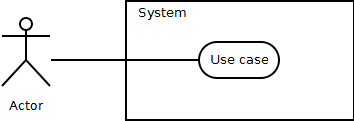
Figure 2 shows a general example of a use case diagram, displaying an actor, system boundary, use case and a releationship between the actor and the use case.
2.2.2 Quality attribute requirements
Quality attributes are related to several aspects of a software system. These include the system qualities itself, which we will discuss in this article, but also business qualities like cost, time-to-market and integration with legacy software, and finally architecture qualities like correctness and completeness. System quality attributes can be documented using quality attribute scenarios. Len Bass et al. [1] suggest a format to describe quality attribute requirements, which we will apply here as well. This format is explained in table 2. Figure 3 shows the parts of a quality attribute scenario (based on [1]).
| Characteristic | Explanation | Example |
| Stimulus | The stimulus is the event that arrives at the system, causing the incentive for creating a quality attribute requirement. | Read request. |
| Stimulus source | The stimulus source is the author of the event arriving at the system. | External: system users. |
| Response | The response captures how the system should respond to the incoming event. | At the entrance point for requests to the system, a queue with limited size is introduced to ensure efficient throughput to the rest of the system. Paralellism is introduced to cope with a large number of read requests to the database. A scheduler applies a earliest-deadline first scheduling policy to deal with incoming requests. Read-only replicas of the database are added to different nodes to distribute database access. |
| Response measure | The response measure is a metric to determine whether or not the response satisfies the quality attribute requirements for the given event. | There is a minimum of 50 read requests per second that the system needs to be able to handle. |
| Environment | The environment of a requirement is the context or state in which the event occurs. | Normal and overload operation. |
| Artifact | The artifact represents the part of the system that is affected by the event. | Persistent storage facilities and communication channels. |
For each type of system quality attribute, e.g., availability, performance, modifiability, security, et cetera, the scenario may include specific characteristics. For example, the environment for modifiability will typically be during development, whereas performance and availability environments are situated at run time. Len Bass et al. [1] describe each of these quality attributes in more detail.
2.3 Result
The full requirement analysis and domain model can be found here (link to pdf). You are welcome to compare the result with your own solution and provide some feedback on this analysis. Note that the non-functional requirements in the last section are somewhat generic. In normal circumstances these are the result of discussions with the stakeholders and other analysts.
3. Synthesis
3.1 Prioritizing requirements
In order to obtain an optimal design in terms of the requirements, it is imperative that the requirements, functional as well as non-functional, should be prioritized as it may possible that certain trade-offs will have be made. Identifying the most important ASRs is done by consulting the project’s stakeholders and should be done before starting with the actual architectural design of the software system.
Once the designing takes off, the ASRs with the highest priority should be addressed first, before ASRs with lower priority, or at least in a way that their impact is not affected. Try to complete the non-functional requirements first, if possible in combination with related functional requirements. A structured approach for designing a software architecture is attribute-driven design, which will be discussed further.
3.2 UML for architectural modeling
3.2.1 Components
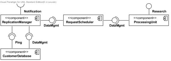
A software architecture is typically described using one or more component diagrams. “A component is an autonomous unit, encapsulated units within a system or subsystem, that provides one or more public interfaces” [4]. Components are represented using a box with a component symbol in the top right corner. A provided interface is shown using the lollipop notation (full circle), while the usage of an interface is shown using the socket notation (half circle), as illustrated by the example in figure 4.
3.2.2 Nodes
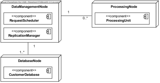
The physical distribution of components of a software architecture across different computational nodes can be described using a deployment diagram. Depending on the amount of detail required, you can make a distinction between device nodes (e.g., a computer or mobile phone) and execution environment nodes (e.g., an operating system, virtual machine, web browser, and so on). Also connections between nodes (communication paths) can be labeled with the protocol used over each communication channel (e.g., HTTP, SOAP, and so on) [5].
For this project we will apply a simplified version of the deployment diagram. Figure 5 shows an example of a deployment diagram based on the component diagram in figure 4.
3.3 Techniques : tactics and patterns
In order to fulfill quality attribute requirements, there is often more than one option to design the system’s architecture. Many of these design alternatives can be reused in other architectures, leading to a repository of techniques to address the needs of certain types of quality attributes. “A tactic is a design decision that influences the achievement of a quality attribute response” [1]. A design pattern on the other hand, consists of a general problem description, a solution structure and rationale that binds them [3].
TODO : create a document with a selection of tactics and patterns.
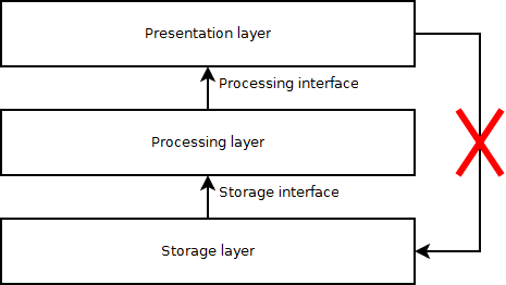
When going from the domain model to a software architecture, applying tactics along the way, you will generally develop a system that is subdivided into different parts. In order to maintain oversight of how these parts relate to each other, there is a need to find meaningful relationships among them. Layers are collections of parts of the architecture with a distinct and specific responsibility. As a result, each layer should encapsulate a certain functionality of the system with a corresponding interface, allowing these parts to evolve independently [3]. A layered design also implies that the dependencies of each layer are top-down, e.g., a storage layer should depend on the presentation layer, as illustrated in figure 6.

Figure 6 : Dependencies between layer are top-down, i.e., the storage layer should not depend on the presentation layer.
3.4 Method : attribute-driven design
There are various ways in which techniques can be applied in order to build an architecture. A structured method for doing this is Attribute-driven design (ADD). Attribute-driven design is a method for designing software architectures. This method consists out of a series of steps over which the designer can iterate, each time decomposing the architecture into greater detail, according to quality attribute and functional requirements [1].
The five steps of the ADD method are as follows [1]:
- Choose an element of the system to design;
- Identify the ASRs for the chosen element;
- Generate a design solution for the chosen element;
- Inventory remaining requirements and select the input for the next iteration;
- Repeat steps 1 to 4 until all the ASRs have been satisfied.
It is important to note that the objective of designing a software architecture is that the architecture meets all or at least as many as possible of the requirements. With this in mind, the method used to achieve this objective is irrelevant. Methods such as ADD are only there to help you achieve these objectives in a clear and structured way. If done correctly, working with a free form method is just as good.
3.5 Resulting architecture
NOTE : The rest of this article is still under major construction.
The final architecture can be found here… TODO …
4. Final thoughts
…
References
[1] L. Bass, P. Clements and R. Kazman, 2013, “Software Architecture in Practice”, Third Edition, Addition Wesley, 589 pages.
[2] A.C.A IT Solutions, E. Steegmans, S. Van den Enden and C. Verhulst, 2012, “Requirements analysis of complex software systems”, KULeuven/A.C.A IT Solutions, collection of lectures an requirement analysis (2013).
[3] F. Buschmann, K. Henney, D.C. Schmidt, 2007, “Pattern-oriented software architecture – A pattern language for distributed computing”, Volume 4, John Wiley & Sons, Ltd.
[4] D. Bell, 2004, “UML basics: The component diagram”, online, available at: http://www.ibm.com/developerworks/rational/library/dec04/bell/
[5] C. Larman, 2005, “Applying UML and Patterns : an introduction to object-oriented analysis and design and iterative development”, third edition, Pearson Education, Inc., 703 pages.


